
Slip Dependent Resistance Starter (Rotor Controller) For Slip ring Induction motors –Starting.Back
Range:- 2.5 KW, 415 V to 6,000 KW, 3.3 KV / 6.6 KV / 11 KV.
 Generally Slipring Induction Motors are used for applications which needs High Starting Torque & same is achieved by connecting additional starting resistance in the rotor circuit. The resistance needs to be reduced continuously in steps to increase the speed of the Motor so that the required torque is maintained.
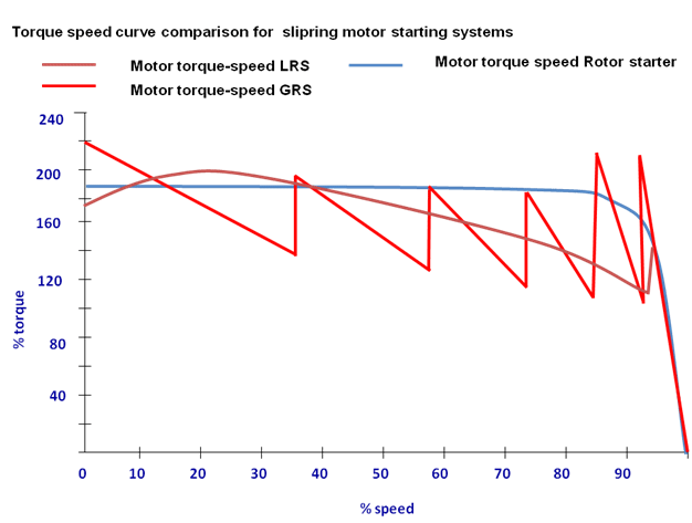
Slip dependent Rotor Resistance Starter / Controller are designed with lossy core & based on Rotor frequency dependant resistance design. This provides a low starting current with automatically reducing resistance which is inversely proportional to motor speed to provide enough starting torque & accelerate the motor with driven equipment to full speed smoothly without Electrical & Mechanical jerks.
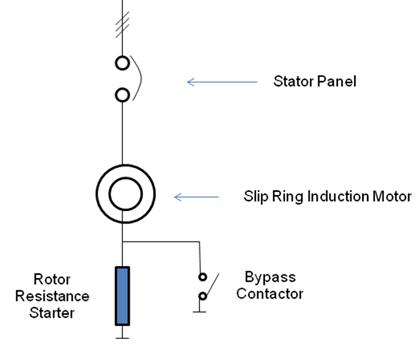
Slip dependent Rotor Resistance Starter is connected to the Rotor Terminals of the motor, so that the starting current is limited to a low value with a high starting torque.
Motor acceleration is smooth, step less and jerk less, as resistance reduction is step less and automatic. After reaching motor to full speed, Rotor Starter will be out of circuit with the help of inbuilt bypass contactor and during running motor will be acting as Squirrel cage induction motor .
These starters sense zero-speed automatically and offer high value (100%) of resistance at every new start . Thus avoid motor damage.
 The Rotor Starter is designed in such a way that the resistance offered by it is frequency dependent.
When the motor starts from zero speed the rotor frequency equal to supply frequency and the Rotor Starter resistance is maximum.
The Rotor Starter is designed in such a way that the resistance offered by it is frequency dependent.
When the motor starts from zero speed the rotor frequency equal to supply frequency and the Rotor Starter resistance is maximum.
This value is decided as follows :-
The rotor voltage of the slipring motor is governed by the following equation.
VR = s x RVss where
VR = Rotor voltage at slip s
s = per unit slip
RVss = Rotor voltage at standstill
With the increase in motor speed the rotor voltage decreases. Thus if the rotor current is to be maintained constant for constant torque, the starting resistance has to be decreased as the motor accelerates.
R RS/Ph = [(RVss/1.73) / (RA x p.u.Torque)]
where R RS/Ph = equivalent star resistance of Rotor Starter in ohms
RVss = Rotor Line voltage at standstill in Volts (rated).
1.73 = Line to phase conversion factor
RA = Rotor current in amps (rated).
p.u.Torque = Desired Motor torque at standstill per unit value
The reduction in Rotor Starter resistance with increase in motor speed (decrease in rotor frequency) is automatic and stepless. The motor and driven equipment thus reaches to full speed steplessly.
Salient Features:
 • Slip dependant Resistance provides automatic resistance variation during acceleration.
• Low Starting current.
• High starting torque.
• Built in bypass contactor.
• No moving parts & stepless cutting of Resistance.
• No maintenance.
Range: 2.2 KW/415 V to 6,000 KW/3.3 KV, 6.6 KV, and 11 KV.
Data Required for Designing Starting Current:
|
|
Applications:
Cement industry - Ball mills, Wagon unloaders, Cement mills, Conveyors etc…
Steel industry - Ball mills, Conveyors etc…
Mines - Crushers, Conveyors, Pumps etc…
Sugar industry - Pumps, Fibrisors, Cutters, Levellers & applications which requires high starting torque.